Showing posts with label 3D printing. Show all posts

Thursday, August 15, 2019

Arduino Project One: Revived - and another detour into 3D printing

The last installment in the story of my Arduino-controlled garage door opener was in November 2017, almost two years ago. The project stalled, not for any reasons of its own, but because of the distractions of everyday life. Now I can finally get back to it.

I may have changed the hardware, switching from an Arduino to a Raspberry Pi. I have good reasons for that, which I'll tell you in a later post. Today, I want to revisit the subject of 3D modeling software.

You will recall that in my previous article about 3D CAD, I mentioned SolidWorks, Tinkercad, SketchUp, Wings 3D, and Microsoft 3D Builder. I haven't tried SolidWorks, because it costs money and I'm cheap. I tried the other four alternatives, and all of them had serious shortcomings. Tinkercad and 3D Builder were so inadequate that I couldn't even take them seriously. Wings 3D is very powerful, but it has a painful and steep learning curve, and all I want to do is design and 3D-print a small enclosure for my project. SketchUp has the power I need, but some of the features I really want to access are hidden behind a paywall.

So, back to the (ahem) drawing board I went. This time, I found just what I was looking for.

(Yet another detour: I've gotten so used to the Linux command line, that I do a lot of graphics work directly in text files. I mean, I write web pages in raw HTML/Javascript/MarkDown/other stuff. I write formatted and typesetted technical documents in LaTeX. For business and technical graphics, I use GraphViz. I use the command-line version of ImageMagick to manipulate existing images. 

And back in the Good Old Days, I used to use the DOS version of WordPerfect with "Reveal Codes" turned on, and I would edit the codes manually. Also back in the good old days, before WISYWIG editors, and before I learned LaTeX, I used to use troff and Interleaf LISP to create typesetted documents. Oh yeah, and I used to write raw HPGL and Logo to do vector graphics - you know, line drawings. Stone knives and bearskins. Old man's voice: "And we liked it! *ptui*")

All of that, just to say that I'm very comfortable with manipulating text-based input to produce graphical output. So I happened across a beautiful little 3D CAD program called OpenSCAD. 

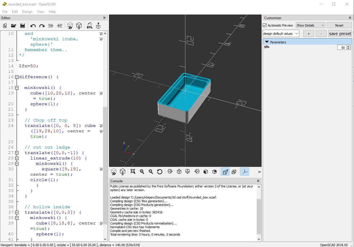
An OpenSCAD screenshot
Another OpenSCAD screenshot, showing the three panes

OpenSCAD doesn't look like much. It has a window with three panes. On the left is the Editor, where you write the text that defines your part: "Put a cube here. Put a cylinder there. Drill a hole in the cylinder." In the center is the Viewer, where you can see your creation from different angles and at different distances. On the right is the Customizer, a neat little thing you can use to modify your design on the fly without having to rewrite the text in the Editor window.

Creating a model in OpenSCAD is like writing a program. If you've used modern scripting languages like Python or JavaScript, it will feel familiar to you. Pressing F5 or F6 to draw your design is like compiling a program. If you've used compiled languages like C or C++, this will also feel familiar to you. And if you get the programming wrong, OpenSCAD will give you an error message and point you to the line where the error was detected. If you've ever done any programming in your life, I'm certain that this will feel familiar to you.

One of the things that I like best about OpenSCAD is that you can minimize the Editor and Customizer panes, leaving just the Viewer pane, and do your editing in your own favorite editor, in a separate window. Being a Vim fan, I open a terminal window and bang away in Vim. Every time I save the file, OpenSCAD detects that the file has changed, and it computes and displays the new object.

OpenSCAD in use. That's my GVIM editor on the left.
(I'll tell you about the hardware in the enclosure in a later post.)
OpenSCAD can export shapes in a variety of file formats, the most important of which is STL (short for stereolithography, a fancy word for "3D printing"), the format preferred by 3D printing services. Cura LE, from Lulzbot, takes an STL file and converts it into the "slices" required by a 3D printer.

Cura LE (Lulzbot Edition)

Now, here's a new player in the game: FreeCAD. One OpenSCAD user reported that OpenSCAD can occasionally mess up an STL file, and the model will not render properly in Cura. He suggests using FreeCAD as an intermediary between OpenSCAD and Cura.

FreeCAD is a relative newcomer to the 3D design world. It's actually been around since 2002, but it didn't become a serious contender until Release 0.14, in 2014. Even today, at Release 0.18, its makers warn that it's still not ready for prime time, but it's a very good parametric 3D modeling package.

FreeCAD screenshot


(Very technical aside: FreeCAD uses the parametric 3D design paradigm, while OpenSCAD uses the constructive solid geometry (CSG) paradigm. I barely know what those words mean, but I do know that my brain wraps more easily around CSG than parametric design. You may feel differently, and if you do, then you should skip OpenSCAD and use FreeCAD directly. I'm serious.)

So my design path now goes like this:
1. Design the thing using OpenSCAD.
2. Import the SCAD file into FreeCAD, and export it as an STL file.
3. Open the STL file in Cura LE and prepare it for printing.

It works for me. And the price is right. 

If I weren't so cheap, I could spend real money and get one piece of software that does it all for me. But if I had that much money, I'd also buy my own 3D printer. And a OneWheel.

Postscript: Are you wishing I had included a weblink for something that I mentioned? Like SketchUp? Or ImageMagick? Some of these items have links in my previous post on this subject. For the others, you'll have to do a Web search. I'm sorry. I got tired of typing.


To read the other postings about this project, click here and scroll to the end.

Sunday, November 26, 2017

Arduino Project One: A detour into 3D printing

This is a sidebar to the main project thread. This is all about 3D printing.

By the way, as this entry shows, I'm a babe in the woods when it comes to 3D printing, both the software used to create the models, and the procedure to transfer the model to a printer and to print them. Advice from my readers — knowledgeable and useful advice — would be appreciated. Feel free to add a comment.

In my last update, "Lots of Progress", I repeatedly mentioned SolidWorks because I thought it was the only game in town.

SolidWorks, really good 3D design SW by Dassault Systemes

Hah.

Our local library has two 3D printers. They suggest Tinkercad for casual 3D design work, Sketchup for more serious 3D design work, and Cura LulzBot Edition for printing your design on one of their LulzBot printers.

Tinkercad, by AutoDesk (that's a Raspberry Pi case)
Sketchup, by Trimble, Inc. (this screenshot is from when it was a Google product)
Cura LE (Lulzbot Edition)


Know what? All of those software packages are free. Actually, Sketchup is available in a free and a Pro ($695 - cough) version.

Sketchup has grown up since Google bought it from that little company in Boulder and encouraged people to use it to plant structures all over Google Earth.

So now I have my 3D printing toolpath defined. As with Corona SDK, I'm sort of familiar with the technology from my computer-game-programming days. I'm sure it's come a long way in 12 years, but it's nothing I can't pick up quickly.

UPDATE, THE NEXT DAY:

Hey! I already have Wings 3D on my computer. It's part of my game-programming toolpath! It can export StereoLithography (.STL) files, the preferred file format for Cura LE. Wings 3D is open source and supported by a huge community.

Wings 3D, a powerful 3D modeler used by the gaming and CGI industries.

I may not need to install any new software to do my 3D designs. We'll see ...

UPDATE, THREE DAYS LATER:

I totally ignored 3D Builder, an app first included in Windows 8.1 and currently part of Windows 10. It looks like 3D Builder is for the casual user, similar to Tinkercad. Most screenshots I've found are for toys and trinkets, but here's a not-so-casual design that looks pretty impressive.

3D Builder by Microsoft, now an integral part of Windows 10

If you don't use 3D Builder, then it and its companion apps, such as Paint 3D, are simply a waste of space on your hard disk. But if they're there and they're free, they may be worth a look.

Searching online for information on 3D Builder, I haven't found anything written about it (I mean, like reviews or tutorials) that is all four of these:
  1. current
  2. serious and useful
  3. written by a serious user, not just a fan or a professional reviewer
  4. offered by a third party (not written by Microsoft or published on a Microsoft page)
I welcome any serious and useful input from my readers, about 3D Builder.

UPDATE, 15 AUGUST 2019: Two years later, the 3D design landscape has changed. As I finally sit down to design the enclosure for my Arduino project, I re-review my toolset and make a few changes of my own. Read about it here.


To read the other postings about this project, click here and scroll to the end.

Arduino Project One: Lots of progress

Introduction

I got to put a lot of time into the project this weekend, and I got some cool stuff done. I ... well, here are two pictures for you, and then the details.

Things glowing in the dark

Lit by a desk lamp - I have to learn to take better pictures.

Hardware fully assembled

I put all the hardware pieces together. In the picture above, you will see the Arduino stack at the top. You've seen this before.

The breadboard has two new peripherals. First, at bottom center is a 16-by-2 liquid crystal display that I found while looking for jumper wires in the Sunfounder Project Super Starter Kit. This LCD can run with either a 4-bit or an 8-bit interface, plus 2 more digital pins for the RS and Enable signals. 

Second, the little red guy on the right is the Hall Effect sensor. When installed, this will be on the other end of a ten-foot long cable, mounted to the lintel.

You will notice a potentiometer on the left side of the breadboard. That's to control the contrast of the display. This is absolutely necessary with an LCD display. In the final enclosure, I'll use a trim pot that can be adjusted with a jeweler's screwdriver, through a hole in the enclosure.

Arduino software (almost) complete

The Arduino program is almost fully fleshed out. It searches for a Wifi router / access point, connects to it, and displays the SSID (the router's name) and its own IP address. Internally it has a list of access points, and cycles through them until it makes a connection.

In case of power failure, the Arduino program restarts, and with any luck the ESP8266 will have saved the connection information from before the power failure. If not, it will take several minutes for the router(s) to reboot, so the ESP8266 will count down 10 minutes on the display and then try again.

Once it has a connection, it starts a TCP server and opens a socket on an out-of-the-way port, to listen for clients. Every ten minutes it pings the router to make sure the Wifi connection is still good. 

That's where things stand right now.

When a client opens a connection to the server, well, that code is still in skeleton form. Before I can finish it, I have to write a client program in Python or C (or Corona!) to exercise the connection. That's one of the next steps.

The display

This was a bit of serendipity. I'd forgotten that Sunfounder kit came with an LCD. This is the standard 16x2 display based on the common ST7066/HD44780 parallel interface. This is a white-on-blue one with not very good contrast, so I'll buy a white-on-black or red-on-black one for the final product. I'd really like an old-fashioned, dot-matrix alphanumeric, 16x2 red LED display, but I haven't seen any of those for a while.

The display uses 4 digital pins for data, and one each for RS and Enable, so it fits within my pin budget.

Incorporating it into the code was a cinch, thanks to the Arduino LiquidCrystal library.

Detour: Who (or what) is "Eorlingas"?


For those of you who already looked it up on the Web, congratulations. For those of you who didn't even have to look it up ('cause you already knew!), I offer you my deepest regards.

For years, every new computer, callphone and game system in our family has borne the name of a fictional horse. When high-speed Internet finally made it to our neighborhood (yes, children, some of us first got our Internet through the phone line - at 2400 bits per second!), we needed a good name for our router, and we chose Rohirrim, the formal name for the Riders of Rohan, from The Lord of the Rings. Since that time, we have worn out or obsoleted four routers, and we're on our fifth one. It's the Fifth Detachment of the Rohirrim, or FifthRohirrim. 

The architecture of our house is such that the back rooms don't always receive a good signal from the router. I want the router to be hard-wired into our Xbox and our TV, so I can't move it. So, I installed a Wifi repeater in the back of the house. (By sheer coincidence, although I'd love to claim clever planning, this repeater is located about six feet above the garage door opener.) The repeater can't be named after a horse, since it's part of the infrastructure, not a computing device.

"Rohirrim" is an ancient Gondor word. The Rohirrim didn't use that word to identify themselves. In the ancient language of Rohan, they were descended from a king named Eorl, hence they were the Sons of Eorl — the Eorlingas.

I will claim clever planning for that one.

Back on the main road: the Hall effect sensor

I decided to try the ACS712 dev board first, because it has built-in trim pots for Vref and gain. I only had to connect it to 5V, ground, and an analog input on the Arduino. I wasn't happy with its performance at first. The voltage level drifted all around. I finally got it to settle down, but I can't have it drifting like that in real life.

When I finally got it settled down, I used a refrigerator magnet to manipulate it. I got the Vref and gain pots adjusted so that it pegged at 0.0 V without the magnet, and at 5.0 V with the magnet touching the chip.

Some voltage level in the circuit is floating. I don't understand the circuit well enough to fix it yet. Maybe I need to put a load (you know, a resistor) between the two current input pins.

Other than that, the sensor just works without complaint or fuss. Clearly, I have more homework to do before I can use it in real life, but this weekend's results were promising.

It needs a case, an enclosure

I've been thinking about this for a while. I'm going to have to put the Arduino in a case.

All of the Arduino Uno R3 enclosures I've found so far are for just the Arduino Uno R3 board. Once you add a shield to your Arduino, it outgrows the enclosure.

A generic project box might be okay, but it can't be metal, because of the Wifi.

I thought of 3D printing one. I don't know SolidWorks, which I think is what everyone uses, so I'd have to learn SolidWorks. I looked for ready-made 3D printable designs, and the first one I found was, I'm really sorry to say this, ugly. 

Okay, I just looked again, and there are some better-looking ones out there. None of them solve my height issue, but if I can get their source and manipulate it in SolidWorks or something, then I can take care of that myself.

I also need to include openings for: the LCD, the contrast adjustment for the LCD, and any LEDs I want to make visible.

I think that making the enclosure, and fitting everything in it, is going to be more work than the hardware and software parts of the project. Maybe I'll just use a cardboard box, an X-Acto knife, and clear packing tape. I'm only half-kidding.

The sensor needs an enclosure too

I can't just nail the Hall effect sensor to the beam in the garage. It will be exposed to a rather harsh environment. I may need to 3D print a case for it as well.

Alternatively, I could encapsulate it in potting compound. That would be just as good - but I'd have to find a way to include mounting holes. And whatever I do has to be nonmetallic, or at least nonmagnetic or nonferrous. Hmm. That will take more thinking.

What's next

I've made good progress so far. Here's what I still need to do

  1. Write a TCP client in Python or C, to exercise the server.
  2. Port that TCP client to an Android app, using Corona SDK.
  3. Finish the Arduino code:
    1. Hall effect sensor
    2. Debug the TCP client-handling code
  4. Finish the Android app as well.
  5. Get a real LCD display.
  6. Design and fabricate enclosures for the Arduino stack and the sensor.
  7. Assemble the whole thing.
Other items that come to mind:
  1. Try the breadboard design in the garage before I commit to a final design.
  2. Run Wireshark while the server is running, to see who tries to call my Arduino.
  3. Configure my router to allow passthrough only on the designated port, or from designated clients.
  4. Exercise the challenge-and-response algorithm.
  5. Document the whole thing.


To read the other postings about this project, click here and scroll to the end.