Showing posts with label 3D. Show all posts

Thursday, August 15, 2019

Arduino Project One: Revived - and another detour into 3D printing

The last installment in the story of my Arduino-controlled garage door opener was in November 2017, almost two years ago. The project stalled, not for any reasons of its own, but because of the distractions of everyday life. Now I can finally get back to it.

I may have changed the hardware, switching from an Arduino to a Raspberry Pi. I have good reasons for that, which I'll tell you in a later post. Today, I want to revisit the subject of 3D modeling software.

You will recall that in my previous article about 3D CAD, I mentioned SolidWorks, Tinkercad, SketchUp, Wings 3D, and Microsoft 3D Builder. I haven't tried SolidWorks, because it costs money and I'm cheap. I tried the other four alternatives, and all of them had serious shortcomings. Tinkercad and 3D Builder were so inadequate that I couldn't even take them seriously. Wings 3D is very powerful, but it has a painful and steep learning curve, and all I want to do is design and 3D-print a small enclosure for my project. SketchUp has the power I need, but some of the features I really want to access are hidden behind a paywall.

So, back to the (ahem) drawing board I went. This time, I found just what I was looking for.

(Yet another detour: I've gotten so used to the Linux command line, that I do a lot of graphics work directly in text files. I mean, I write web pages in raw HTML/Javascript/MarkDown/other stuff. I write formatted and typesetted technical documents in LaTeX. For business and technical graphics, I use GraphViz. I use the command-line version of ImageMagick to manipulate existing images. 

And back in the Good Old Days, I used to use the DOS version of WordPerfect with "Reveal Codes" turned on, and I would edit the codes manually. Also back in the good old days, before WISYWIG editors, and before I learned LaTeX, I used to use troff and Interleaf LISP to create typesetted documents. Oh yeah, and I used to write raw HPGL and Logo to do vector graphics - you know, line drawings. Stone knives and bearskins. Old man's voice: "And we liked it! *ptui*")

All of that, just to say that I'm very comfortable with manipulating text-based input to produce graphical output. So I happened across a beautiful little 3D CAD program called OpenSCAD

An OpenSCAD screenshot
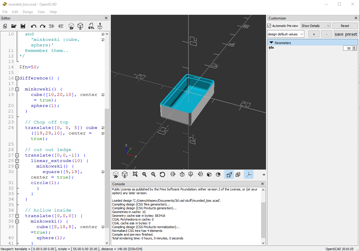
Another OpenSCAD screenshot, showing the three panes

OpenSCAD doesn't look like much. It has a window with three panes. On the left is the Editor, where you write the text that defines your part: "Put a cube here. Put a cylinder there. Drill a hole in the cylinder." In the center is the Viewer, where you can see your creation from different angles and at different distances. On the right is the Customizer, a neat little thing you can use to modify your design on the fly without having to rewrite the text in the Editor window.

Creating a model in OpenSCAD is like writing a program. If you've used modern scripting languages like Python or JavaScript, it will feel familiar to you. Pressing F5 or F6 to draw your design is like compiling a program. If you've used compiled languages like C or C++, this will also feel familiar to you. And if you get the programming wrong, OpenSCAD will give you an error message and point you to the line where the error was detected. If you've ever done any programming in your life, I'm certain that this will feel familiar to you.

One of the things that I like best about OpenSCAD is that you can minimize the Editor and Customizer panes, leaving just the Viewer pane, and do your editing in your own favorite editor, in a separate window. Being a Vim fan, I open a terminal window and bang away in Vim. Every time I save the file, OpenSCAD detects that the file has changed, and it computes and displays the new object.

OpenSCAD in use. That's my GVIM editor on the left.
(I'll tell you about the hardware in the enclosure in a later post.)
OpenSCAD can export shapes in a variety of file formats, the most important of which is STL (short for stereolithography, a fancy word for "3D printing"), the format preferred by 3D printing services. Cura LE, from Lulzbot, takes an STL file and converts it into the "slices" required by a 3D printer.

Cura LE (Lulzbot Edition)

Now, here's a new player in the game: FreeCAD. One OpenSCAD user reported that OpenSCAD can occasionally mess up an STL file, and the model will not render properly in Cura. He suggests using FreeCAD as an intermediary between OpenSCAD and Cura.

FreeCAD is a relative newcomer to the 3D design world. It's actually been around since 2002, but it didn't become a serious contender until Release 0.14, in 2014. Even today, at Release 0.18, its makers warn that it's still not ready for prime time, but it's a very good parametric 3D modeling package.

FreeCAD screenshot


(Very technical aside: FreeCAD uses the parametric 3D design paradigm, while OpenSCAD uses the constructive solid geometry (CSG) paradigm. I barely know what those words mean, but I do know that my brain wraps more easily around CSG than parametric design. You may feel differently, and if you do, then you should skip OpenSCAD and use FreeCAD directly. I'm serious.)

So my design path now goes like this:
1. Design the thing using OpenSCAD.
2. Import the SCAD file into FreeCAD, and export it as an STL file.
3. Open the STL file in Cura LE and prepare it for printing.

It works for me. And the price is right. 

If I weren't so cheap, I could spend real money and get one piece of software that does it all for me. But if I had that much money, I'd also buy my own 3D printer. And a OneWheel.

Postscript: Are you wishing I had included a weblink for something that I mentioned? Like SketchUp? Or ImageMagick? Some of these items have links in my previous post on this subject. For the others, you'll have to do a Web search. I'm sorry. I got tired of typing.


To read the other postings about this project, click here and scroll to the end.

DraftSight is no longer free

Remember when I wrote that article about DraftSight, and I was excited because it was an AutoCAD clone, but it was free? And remember when I wrote some follow-up articles uncovering all of DraftSight's hidden 3D design features, even though Dassault Systèmes told the world that it was just 2D drafting software? Well, DraftSight has grown up.

DraftSight 2018 is the last free version of DraftSight. Starting with DraftSight 2019, all future versions will cost money. Not only that, but all pre-2019 versions of DraftSight will stop working, or "cease to run", as the announcement says, after December 31, 2018.

Click here for the official announcement. (In case that link stops working, here's what it looked like in October 2018.)
DraftSight announcement


Dassault Systèmes are, of course, perfectly justified in charging money for DS. DS is professional-quality software, that's for sure. It was written by hired engineers in a for-profit company, and they deserve to make a profit on it. Not only that, but DS 2019 now officially includes a full complement of 3D design tools; it's billed as "a 2D drafting and 3D design experience."

And, considering the prices of comparable software, DS 2019 may still be a bargain, compared to the competition:

  • $100/yr for the Standard version, 2D only, for hobbyists, students and teachers.
  • $200/yr for the Professional version, still 2D only.
  • $500/yr for the Premium version, which includes the 3D tools.
Are there free alternatives? Well, sure, all of the AutoCAD clones that existed before DraftSight are still there. But the state of the art has progressed since DraftSight was first released in 2011. Now, designers are doing 3D CAD and then converting their creations into data files for 3D printing, CNC milling, and other automated manufacturing processes. But there's still a need for the 2D drawings, and so the higher-quality 3D CAD packages (the ones that cost money) can also generate the 2D drawings from the 3D models.

Next, I'm going to tell you about the new CAD solution that I'm going to use.

Friday, November 4, 2011

DraftSight 3D: How to

This is more of a quick reference guide than a tutorial.  If you follow the instructions given here, you'll be able to experiment with 3D in DraftSight and discover new stuff.  When you discover something that might be useful here, please send me a comment.  I won't post it as a comment, but if it's useful I will add it to the main text of this article - I'll add your name or ID at the bottom of the article.

What can you do with a DraftSight 3D CAD model?
Unfortunately, right now you can't do much besides play with it inside DraftSight.  Somebody please enlighten me.
When you save it as a DWG file, it saves all the 3D data.  You can confirm that by exiting and restarting DraftSight, and then reloading the DWG file.
But the 3D doesn't import into Creo Elements/Direct Modeling Express.
I don't know about MilkShape or UVMapper yet.
The free version of DraftSight doesn't let you export the file in a different format.
???

What is the CCR?
You'll see the initials "CCR" in a lot of the DraftSight documentation.  CCR stands for Cartesian coordinate reference.  It's the little X-Y widget in the lower left corner of the Model view when you first start up DraftSight.  There's actually a Z axis on it as well as the X and Y axes, but you won't see it until you start "rolling the view."  The CCR will help you maintain your orientation when you're viewing objects in 3D.

How to view in 3D
Viewing things in 3D is easy.  You can even view a 2D drawing in 3D!  That's kind of funky and not really useful, but it's fun to do once or twice.
1. From the main menu, select View --> Constrained Orbit.
  - OR -
  From the command line, type ROLLVIEW and press Enter.
  The mouse cursor changes to a circle thingy.
2. Hover the mouse over an object in your drawing.  Hold down the left mouse button.  The mouse cursor changes to two 3D circle thingies.
3. With the left mouse button still down, move the mouse.  You'll get the hang of it.
4. To return the mouse function to normal, press Esc, press Enter, or right-click the mouse.  This doesn't return the 3D view to normal.

How to return the 3D view to normal
Here's the really quick way:  At the command line, type -V O T. That's short for -Views, Orthographic, Top.  The dash is important:  without the dash, you get the dialog box.

(UPDATE, 9 Feb 2012: Here's an even quicker way, pointed out by an alert reader: type PLAN and press Enter. It worked in AutoCAD, and it works in DS too.)

Here's the conventional way:
1. Either type V (short for VIEWS) and press Enter, or select View --> Named Views from the main menu.
2. In the dialog box, select View Type --> Defaults.  Select Top view, and click OK.

By "normal" I mean:
- You get a 2D view, showing the XY plane.  The CCR shows X and Y axes only.
- A Zoom Fit is automatically executed, so everything shows in the drawing area.
- This doesn't put the CCR at (0,0,0), but it does put it in the lower left corner of the drawing area.

How to create wireframe shapes
1. From the command line, type 3D and press Enter.
2. You can select from 9 different shapes:
Box - specify Length (+X or RIGHT), Width(+Y or UP), Height (+Z or into screen), and rotation about Z-axis (this is rotation in the 2D plane, with 0 being +X and numbers increasing towards +Y.  You can also make a cube and a square box using the C shortcut after Length or Width.
Cone
Dish
Dome
Mesh - specify four corners of a rubber sheet, and how many segments you want between the corners.  M and N are difficult concepts to explain, but they'll make sense when you see them.
Pyramid
Sphere
Torus
Wedge

How to extrude 3D shapes from a 2D cross section
1. Create the 2D shape.  It doesn't have to be on the Z=0 plane, but it all has to have the same Z value (that is, parallel to the Z=0 plane.
2. From the command line, type EXTRUDE and press Enter.
3. Click the 2D shape.
4. Either enter a numeric number (positive or negative) for the extrusion height in the Z direction,
  - OR -
  If you are viewing the shape obliquely (from ROLLVIEW or something), you can just move the mouse to the extrusion height you want, and left-click to set it.

How to rotate and stretch 3D shapes in 3 dimensions
???

How to create primitives
These are all in the Draw-->Mesh submenu.
2D Solid - Also the SOLID command.
This creates a shape with faces, not just a wireframe.
If you're using the mouse, you specify 3 corners of a triangle, or 4 corners of a quadrilateral - but if your specifying a quadrilateral, don't go in a circular motion.  You have to go in a zigzag.  If you go in a circular motion, you get the dreaded butterfly effect.  After you specify 3 corners and press enter, it draws a triangle.  After you specify 4 corners, it draws a quad.  The last 2 points now become the 1st and 2nd points of the next side, and you can specify new 3rd and 4th points.  In this way, you can create a long polygon of quads all stitched together.
3D Face - Also the FACE command.
I'm not clear on the difference between this and 2D Solid.  They both seem to do the same thing for me.
3D Mesh - also the MESH command. 
I explained this earlier.
Revolved - also the REVOLVEDMESH command.< This creates a solid of rotation.  Draw a 2D shape you want to use as your revolved surface, and draw a straight line (or pick a straight feature, like the edge of a box) to use as the axis of rotation.  The elements don't have to be on the Z=0 plane, or any other plane; nor do they have to be coplanar.  Unfortunately, I don't know the Setup option to give you more than 6 segments in the rotated solid.<
Tabulated - also the TABULATEDMESH command.
This is like EXTRUDE, only its direction and distance of extrusion is not dependent on the Z axis. 
1. Create a 2D shape on a horizontal (Z = constant) plane. 
2. Draw a line the direction (3D) and distance you want to go. 
3. Execute the command from the menu or the command line.
4. "entity for path curve" is the 2D shape you want to extrude.
5. "Entity for direction vector" is the line defining distance and direction.
Edge - also the EDGEMESH command.
This command takes four "open" entities (line, arc, polyline, spline, etc.) and draws a rubber-sheet mesh between them all.  Their ends have to be touching, to make 4 vertices.
Ruled - also the RULEDMESH command.
This command takes two entities and joins them to make a solid with the two entities as faces.
1. If one entity is a point and the other a closed element (rectangle, circle, polygon) then you end up with a cone or a prism.
2. If one entity is a point and the other an open element (line, spline, curve), you end up with a fan.
3. If both are open elements, you end up with the rubber sheet mesh.
4. If both are closed elements, you end up with a cool 3D adapter thingy like the vent hood above the grill at a Mongolian Barbecue restaurant.

How to create 2D shapes with some thickness to them, and on a different plane
The ZPLANE command lets you add thickness to your 2D objects.  It also lets you draw on a different Z plane than the default Z=0 plane.
1. From the command line, type ZPLANE and press Enter.
2. Type the value for the new Z plane, then press Enter.
3. Type the thickness for the objects you're about to draw, then press Enter.

How to join primitives to make 3D objects
???

How to join 3D shapes and objects to make more complicated objects
???

How to color faces, and how to hide unseen surfaces
The Hatch/Fill function can be used to select and color faces.  I suggest just using the "fill" capability.  Unfortunately, selecting the face to color doesn't work reliably for me.  I guess I haven't discovered the trick yet.
1.  Click on the Hatch/Fill icon in the menu on the left side of the drawing area
- OR -
Select Draw --> Hatch/Fill from the main menu
- OR -
On the command line, type HATCH and press Enter.
2. In the dialog box that comes up:  in the Type box, select Fill.  In the Colors box, select a color.  You can also change the Style and Orientation.  Don't hit OK yet - it's probably greyed out anyway.
3. In the Boundary settings box, click Specify Points.  The Hatch dialog temporarily disappears, so you can choose a face to color.  Click on any area inside the face, then press Esc or Enter. (WARNING:  THIS DOESN'T ALWAYS WORK!)
3a. While the Hatch dialog is temporarily absent, you can also turn or manipulate the 3D object to find the face you want to color, by selecting View-->Constrained Orbit from the main menu.  When you have finished manipulating the 3D object, press Enter or Esc to return to the view that lets you select a face.
4. After you have selected a face and returned to the Hatch dialog, click OK.

If you know of a more reliable way to select the face to color, please comment on this article. I won't post your comment, but I will edit the article and put your name or ID in the acknowledgements.

How to change the lighting so the 3D item is easier to see
???

Acknowledgements
Thanks to these people who have helped to expand my knowledge of DraftSight's 3D capability, and to make this guide more complete:
Anonymous, for telling me about PLAN.

DraftSight and 3D - it's all in there

Yesterday, I wrote that DraftSight's 3D capability was limited to primitives:  triangles, rectangles, and polygons.  Boy, was I wrong.

UPDATE:  I just wrote a really quick "how to" guide for DraftSight and 3D.  Click here.

For the 3D-disinclined, let me use three real-world objects to help you understand 3D CAD.

First, imagine a wire birdcage, the kind your grandmother uses for her parakeet or canary.  A birdcage is made of a bunch of wires, crossing and intertwining.  They define a region of space - the inside of the bird cage.  CAD programs define a solid object by imagining the surface of it as a bird cage - a bunch of wires crossing each other or connecting with each other.  CAD programs just store all the wire crossings, or vertices (singular vertex, plural vertices), and the wires, or edges, that go from one vertex to another.  You've probably heard of wireframe models or drawings.

Second, imagine a fishnet - a giant fishnet, being dragged through the ocean.  The water and the caught fish pull that net into a certain shape, and that shape can be manipulated by the boat, the current, and the fish (hello, Nemo!).  Another word for "net" is "mesh."  CAD programs also use the terms net and mesh to describe the wireframe drawings.

Finally, think of a Tiffany lamp.  A Tiffany lamp is like a three-dimensional stained glass window.  The lamp maker makes the wire frame first, and then fastens the glass pieces into the frame.  In 3D CAD, the glass pieces are called faces.

3D CAD is a little more complicated than Tiffanly lamps, though, because each face has an "in" side and an "out" side.  Designers have to make sure they get all faces facing (sorry) the right way.

Snooping around, and with a hint from the Internet, I found a couple of tantalizing command-line commands in DraftSight:  EXTRUDE and 3D.  They're definitely worth exploring.  Moreover, the main menu, under Draw --> Mesh, gives an entire list of 3D capabilities.

Conclusion:  Yes. DraftSight has it all in there - vertices, edges, faces, wireframes, meshes, nets - a 2D program with built-in 3D capability.  Now we just have to figure out how to use it all.

Tuesday, November 1, 2011

DraftSight: Scripting and 3D

No, this isn't about how to use scripting to do 3D CAD, although at the end of this article, I point you to the DraftSight help files for some hints on how to do just that.

In my first review of DraftSight, I mentioned that the free version of DS doesn't support LISP macros.  Well, it still doesn't.  I'm not complaining; that was a sound business decision.  Buying the SDK also buys you LISP macro support, and the SDK is not prohibitively expensive.

But if you're willing to get by without the speed of LISP, you can create and run scripts in DraftSight.

For example, suppose you want to draw a circle centered at (5,5) with radius 10.  (I borrowed this example from another online DraftSight help file.)  One way to do this is to type on the command line:

CIRCLE 5,5 10

Another way is to type on the command line:

CIRCLE
5,5
10

(Note the spaces in the first command entry, and the new lines in the second command entry.  The commands are identical in their execution.)

You can use Notepad, Vim, or your favorite text editor to create a script file to do the work for you.  Simply copy and paste either of the above commands into the editor, and save it as "circle55.scr" . (SCR for "script file".)

Now, at the command line, type the command LOADSCRIPT and press Enter.  A "Select File" dialog pops up.  Select your "circle55.scr" file, click Open, and watch the magic.

You can use a script file to automate a sequence of drawing commands that you perform regularly.  Here's an easy way to create that script file:

  1. Perform the command steps that you want to store.
  2. Type CommandHistory to open the separate command history window.
  3. Right-click and select Copy History.
  4. Open an editor program such as Microsoft® Notepad.
  5. Paste the command steps into the editor program.
  6. Save the file as an .scr file.

 (I stole that text from DraftSight's own help file, under Customizing-->Running Scripts-->Running a Script File.)

Now, one of my hobbies and passions is 3D graphics.  I thought DraftSight was just a 2D CAD program, but I kept seeing hints in the documentation to a Z-axis pointer on the Cartesian Coordinate Reference (CCR), that widget that shows up in the lower left of the drawing window.  In addition, the cursor location given in the Status bar is always a 3D coordinate.  It just so happens that DraftSight's help pages include two tantalizing sections, labeled "3D Viewing and Presentation" and "Creating and Modifying 3D Entities."

After I worked through those 2 sections, I can say that yes, DraftSight can draw in 3D.  HOWEVER, the free-as-downloaded version only does 3D primitives:  triangles, rectangles, and polygons of a size that I haven't discovered yet.  Two problems arise from working with primitives:  you often get the "butterfly" shape that the help pages warn you about; and if you create some triangles clockwise and others counterclockwise, their normals point in opposite directions, your solids come out goofy, and the lighting and surface rendering don't work as you expect them to work.

If you want to do complex 3D shapes, you will have to do one of the following things:
  1. A lot of typing.
  2. Buy the additional 3D capability (if it's available - I haven't hunted that far yet).
  3. Buy the SDK and write some 3D macros in LISP.
  4. Write script files instead of LISP macros.
Also note that the free version of DraftSight only saves DWG and DXF files, so you may end up doing some beautiful 3D work and have no way to export it to STL or another 3D format.

Conclusion: It's nice to know that some programming - er, scripting - capability is built into the free version.  And, with respect to 3D, it's also nice to know that I had to direct my explorations into something as complicated as 3D modeling before I found any serious limitations in DraftSight - and even those limitations are just temporary bumps in the road.

CORRECTION, NOVEMBER 4:  It's all in there. DraftSight does indeed have high-level 3D capability.  See this post.

UPDATE, NOVEMBER 9:  For more information on using scripts in DraftSight, see this post.

Tuesday, August 23, 2011

Make a video game! Part Two

In my previous entry, I quoted one of the inventors of the PC as saying that the reign of the PC is over.  Well, Forbes has been saying "The PC is dead" for years now, and the PC still refuses to die.  I think what will eventually happen is that the PC will lose its cachet with household users, and go back into the office and the laboratory whence it came. But it will not die.  After all, you have to develop all those Android and iPod apps on something.

(When I say "PC," I'm including "Mac" in the mix.  Don't get your senstivities all in a twist, okay?  I'm also going to throw laptop and notebook PCs in with the desktop ones - basically, any computing device that uses a keyboard and mouse for input, and a pixellated display for output.)

The latest wrinkle in video and computer gaming is 3D gameplay.  You're all familiar with 3D movies, some recent notable ones being Tangled, Harry Potter and the Installment of Doom, and Captain America.  I only saw Tangled in 2D, although I can imagine that it was spectacular in 3D.  I saw Harry Potter in 3D, and to be honest, it didn't need it.  Don't get me wrong:  the movie was great, the 3D effects were great, but the 3D effects did not enhance the story.  The story is very well told, and it can stand on its own, without the aid of 3D.

Nevertheless, 3D cinema is here to stay.  The moviemakers are doing it right this time, and though I think it's just a recycled fad, I also think it's permanent.  As my Harry Potter experience showed, not everything needs to be 3D, but for some movies, it really makes a difference.

Now 3D is moving out of the movies and into games.  Kenneth Wong writes a thoughtful piece about it in the June/July 2011 issue of Computer Graphics World, called "Seeing Double:  Stereo 3D Moves from Cinema to Game Cinematic and Gameplay."  Okay, that's a long title, but Wong makes a good case for 3D.  He says that it's kind of clunky right now, like the original Atari 2600's sprites were kind of clunky back then, but that it can only get better with time.  The entry point for 3D gaming is "Nvidia's $149 stereo 3D kit, called 3D Vision."  Think of that!  For only a hundred and fifty bucks, you can get a glimpse into the future of gaming.  That sounds  pretty good.  (But you'll need a PC or Mac to do it.)

He quotes Mike Roush, from Gaijin Games (developers of the Bit.Trip game series) as saying '"3D is such a young medium right now. It's just going to get bigger.  Being in the first round of game deveopers to work on stereo 3D is an honor."'

Then he quotes Vernon Wilbert of Digital Domain.  Wilbert notes that every breakthrough or incremental improvement in interactive entertainment (by which Wong means "games") is, as Wilbert puts it, "a push toward the holodeck."  Star Trek fans will understand that reference.  Says Wong, quoting Wilbert:  '"It's getting you one step closer to the holodeck.  Stereo is the gateway to something else."'

Want to make a million bucks? Make a video game!

Two interesting articles appeared this month in two different publications. One was about the eventual decline of the PC, and the other was about the glowing future of 3D video games. These two articles are related, although the authors did not intend it that way.

The first was actually an entry in the "A Smarter Planet Blog" on August 10, 2011, entitled IBM Leads the Way in the Post-PC Era. This article was written by Mark Dean, Chief Technology officer of IBM Middle East and Africa, who was one of the 12 original PC designers 30 years ago (released to the public on August 12, 1981) and a driving force in IBM's PC division until it was sold to Lenovo in 2005.

Dean says:
It may be odd for me to say this, but I’m also proud IBM decided to leave the personal computer business in 2005, selling our PC division to Lenovo. While many in the tech industry questioned IBM’s decision to exit the business at the time, it’s now clear that our company was in the vanguard of the post-PC era. 
I, personally, have moved beyond the PC as well. My primary computer now is a tablet. When I helped design the PC, I didn’t think I’d live long enough to witness its decline. But, while PCs will continue to be much-used devices, they’re no longer at the leading edge of computing. They’re going the way of the vacuum tube, typewriter, vinyl records, CRT and incandescent light bulbs. 
PCs are being replaced at the center of computing not by another type of device—though there’s plenty of excitement about smart phones and tablets—but by new ideas about the role that computing can play in progress. These days, it’s becoming clear that innovation flourishes best not on devices but in the social spaces between them, where people and ideas meet and interact. It is there that computing can have the most powerful impact on economy, society and people’s lives.
It's an interesting concept, and a concept that gains currency when one looks around and sees the profusion of smartphones and tablets.  So many of the tasks that used to require PCs (including laptops and netbooks) have abandoned that dependency.  For example, it's now the custom, when one reaches the summit of one of Colorado's fourteeners (mountains higher than 14,000 feet), to pull out one's smartphone, take a self-portrait on the summit, and post it instantly on Facebook.  That used to require a digital camera, a mini-USB cable, and a PC, and it couldn't be done until the climber came down the mountain and went home.

For another example (and a good segue into the second article), I was part of the start-up of two computer game companies in the 2003-2004 era.  All of our development work was PC-based.  All of the tools were PC-based.  This made sense, because the target platforms for our games were overwhelmingly PCs. (Mac and Linux were Johnny-come-latelys in the gaming world.)  If we were still developing games today, the world would be a lot different.  Our development work could be done as easily on a Mac or Linux box as on a PC, and the target platforms would not be overwhelmingly PCs.  In the intervening years, consoles have made an incredible resurgence, with the Microsoft XBox family, the Nintendo Wii, and the Sony PlayStation family.  In a dramatic shift, more high-end games are played on consoles today than on PCs.

But the market is in rapid flux, and the consoles are now seeing their lunch money stolen by smartphones, iPods, tablets, and the completely ethereal and device-independent Internet.  Okay, so the Internet existed more than 8 years ago - even Web browsers existed more than 8 years ago - but most users did not have a high-speed connection to the Internet.  Now that has all changed.  Even the aforementioned iPods have high-speed processors and high-bandwidth connections to the Internet, which make playing online games a cinch.

How big is the game industry?  Well, it's grown immensely since I first stuck my toe in it.  In the June/July issue of Computer Graphics World (see p. 26 of the print edition), Kenneth Wong cited the following figures:

... The total console, portable, and PC game software industry generated $10.5 billion in 2009.  Of that, PC game software accounted only for $538 million. ...  Total revenues spent on games in the US reached $24 billion in 2010.  PC/Mac game downloads and retail box sales accounted for approximately 19 percent of that ($4.6 billion).  By contrast, console games accounted for close to 43 percent ($10.6 billion).  The rest was distributed among casual game portals, massively multiplayer games, social networks, and mobile devices.

Look at those numbers again.  They contain two hidden statistics, which Wong bypassed because they were irrelevant to the thrust of his article.  But they're worth noting.  First, the $10.6 billion spent on console games alone in 2010 was more than the total spent on all console, portable and PC games ($10.5 billion) a year before.  Second, that third piece of the pie which Wong lumped together as "the rest," was a not-insignificant 38 percent of game sales revenues, or $9.1 billion.

It's easy to look at the video and computer game industry and say that the pond is full, that there's no more room for the little fishies, what with big names like EA Games and Vivendi Universal swimming around.  The truth is that there's still a lot of room for the little fishies, the indie developers.  While much of the innovation goes on in the big companies, and up the road at Pixar and Lucasfilm, the indies are holding their own.  Once in a while, one of them strikes gold (Angry Birds, anyone?).  The gaming industry is still a good place to make a start.

Two companies are worth mentioning here, and I know that my readers can suggest others.

First: Nvidia.  According to Wong, Nvidia has a $149 product called 3D Vision which, when installed on your PC (hey! I guess they're not dead!), allows you to play many of your favorite 2D titles in 3D.  A list of the 2D games that work with 3D Vision is available at http://www.nvidia.com/object/3d-vision-games.html .  There's a lot more to 3D Vision than just a 2D-to-3D retrofit:  Nvidia is serious about their 3D offerings .

Second:  GarageGames.  This is the ultimate indie gamer resource, and the last refuge of the indie gamer.  GarageGames, through their Torque family of game engines (game-creation software, basically) and their user community, has done more to promote indie gamers, on more platforms, than any other company out there.