Showing posts with label Solidworks. Show all posts

Thursday, August 15, 2019

Arduino Project One: Revived - and another detour into 3D printing

The last installment in the story of my Arduino-controlled garage door opener was in November 2017, almost two years ago. The project stalled, not for any reasons of its own, but because of the distractions of everyday life. Now I can finally get back to it.

I may have changed the hardware, switching from an Arduino to a Raspberry Pi. I have good reasons for that, which I'll tell you in a later post. Today, I want to revisit the subject of 3D modeling software.

You will recall that in my previous article about 3D CAD, I mentioned SolidWorks, Tinkercad, SketchUp, Wings 3D, and Microsoft 3D Builder. I haven't tried SolidWorks, because it costs money and I'm cheap. I tried the other four alternatives, and all of them had serious shortcomings. Tinkercad and 3D Builder were so inadequate that I couldn't even take them seriously. Wings 3D is very powerful, but it has a painful and steep learning curve, and all I want to do is design and 3D-print a small enclosure for my project. SketchUp has the power I need, but some of the features I really want to access are hidden behind a paywall.

So, back to the (ahem) drawing board I went. This time, I found just what I was looking for.

(Yet another detour: I've gotten so used to the Linux command line, that I do a lot of graphics work directly in text files. I mean, I write web pages in raw HTML/Javascript/MarkDown/other stuff. I write formatted and typesetted technical documents in LaTeX. For business and technical graphics, I use GraphViz. I use the command-line version of ImageMagick to manipulate existing images. 

And back in the Good Old Days, I used to use the DOS version of WordPerfect with "Reveal Codes" turned on, and I would edit the codes manually. Also back in the good old days, before WISYWIG editors, and before I learned LaTeX, I used to use troff and Interleaf LISP to create typesetted documents. Oh yeah, and I used to write raw HPGL and Logo to do vector graphics - you know, line drawings. Stone knives and bearskins. Old man's voice: "And we liked it! *ptui*")

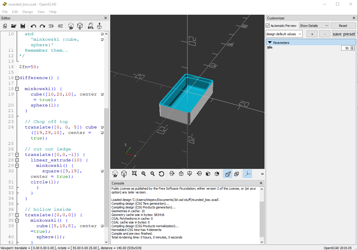
All of that, just to say that I'm very comfortable with manipulating text-based input to produce graphical output. So I happened across a beautiful little 3D CAD program called OpenSCAD

An OpenSCAD screenshot
Another OpenSCAD screenshot, showing the three panes

OpenSCAD doesn't look like much. It has a window with three panes. On the left is the Editor, where you write the text that defines your part: "Put a cube here. Put a cylinder there. Drill a hole in the cylinder." In the center is the Viewer, where you can see your creation from different angles and at different distances. On the right is the Customizer, a neat little thing you can use to modify your design on the fly without having to rewrite the text in the Editor window.

Creating a model in OpenSCAD is like writing a program. If you've used modern scripting languages like Python or JavaScript, it will feel familiar to you. Pressing F5 or F6 to draw your design is like compiling a program. If you've used compiled languages like C or C++, this will also feel familiar to you. And if you get the programming wrong, OpenSCAD will give you an error message and point you to the line where the error was detected. If you've ever done any programming in your life, I'm certain that this will feel familiar to you.

One of the things that I like best about OpenSCAD is that you can minimize the Editor and Customizer panes, leaving just the Viewer pane, and do your editing in your own favorite editor, in a separate window. Being a Vim fan, I open a terminal window and bang away in Vim. Every time I save the file, OpenSCAD detects that the file has changed, and it computes and displays the new object.

OpenSCAD in use. That's my GVIM editor on the left.
(I'll tell you about the hardware in the enclosure in a later post.)
OpenSCAD can export shapes in a variety of file formats, the most important of which is STL (short for stereolithography, a fancy word for "3D printing"), the format preferred by 3D printing services. Cura LE, from Lulzbot, takes an STL file and converts it into the "slices" required by a 3D printer.

Cura LE (Lulzbot Edition)

Now, here's a new player in the game: FreeCAD. One OpenSCAD user reported that OpenSCAD can occasionally mess up an STL file, and the model will not render properly in Cura. He suggests using FreeCAD as an intermediary between OpenSCAD and Cura.

FreeCAD is a relative newcomer to the 3D design world. It's actually been around since 2002, but it didn't become a serious contender until Release 0.14, in 2014. Even today, at Release 0.18, its makers warn that it's still not ready for prime time, but it's a very good parametric 3D modeling package.

FreeCAD screenshot


(Very technical aside: FreeCAD uses the parametric 3D design paradigm, while OpenSCAD uses the constructive solid geometry (CSG) paradigm. I barely know what those words mean, but I do know that my brain wraps more easily around CSG than parametric design. You may feel differently, and if you do, then you should skip OpenSCAD and use FreeCAD directly. I'm serious.)

So my design path now goes like this:
1. Design the thing using OpenSCAD.
2. Import the SCAD file into FreeCAD, and export it as an STL file.
3. Open the STL file in Cura LE and prepare it for printing.

It works for me. And the price is right. 

If I weren't so cheap, I could spend real money and get one piece of software that does it all for me. But if I had that much money, I'd also buy my own 3D printer. And a OneWheel.

Postscript: Are you wishing I had included a weblink for something that I mentioned? Like SketchUp? Or ImageMagick? Some of these items have links in my previous post on this subject. For the others, you'll have to do a Web search. I'm sorry. I got tired of typing.


To read the other postings about this project, click here and scroll to the end.

DraftSight is no longer free

Remember when I wrote that article about DraftSight, and I was excited because it was an AutoCAD clone, but it was free? And remember when I wrote some follow-up articles uncovering all of DraftSight's hidden 3D design features, even though Dassault Systèmes told the world that it was just 2D drafting software? Well, DraftSight has grown up.

DraftSight 2018 is the last free version of DraftSight. Starting with DraftSight 2019, all future versions will cost money. Not only that, but all pre-2019 versions of DraftSight will stop working, or "cease to run", as the announcement says, after December 31, 2018.

Click here for the official announcement. (In case that link stops working, here's what it looked like in October 2018.)
DraftSight announcement


Dassault Systèmes are, of course, perfectly justified in charging money for DS. DS is professional-quality software, that's for sure. It was written by hired engineers in a for-profit company, and they deserve to make a profit on it. Not only that, but DS 2019 now officially includes a full complement of 3D design tools; it's billed as "a 2D drafting and 3D design experience."

And, considering the prices of comparable software, DS 2019 may still be a bargain, compared to the competition:

  • $100/yr for the Standard version, 2D only, for hobbyists, students and teachers.
  • $200/yr for the Professional version, still 2D only.
  • $500/yr for the Premium version, which includes the 3D tools.
Are there free alternatives? Well, sure, all of the AutoCAD clones that existed before DraftSight are still there. But the state of the art has progressed since DraftSight was first released in 2011. Now, designers are doing 3D CAD and then converting their creations into data files for 3D printing, CNC milling, and other automated manufacturing processes. But there's still a need for the 2D drawings, and so the higher-quality 3D CAD packages (the ones that cost money) can also generate the 2D drawings from the 3D models.

Next, I'm going to tell you about the new CAD solution that I'm going to use.

Sunday, November 26, 2017

Arduino Project One: A detour into 3D printing

This is a sidebar to the main project thread. This is all about 3D printing.

By the way, as this entry shows, I'm a babe in the woods when it comes to 3D printing, both the software used to create the models, and the procedure to transfer the model to a printer and to print them. Advice from my readers — knowledgeable and useful advice — would be appreciated. Feel free to add a comment.

In my last update, "Lots of Progress", I repeatedly mentioned SolidWorks because I thought it was the only game in town.

SolidWorks, really good 3D design SW by Dassault Systemes

Hah.

Our local library has two 3D printers. They suggest Tinkercad for casual 3D design work, Sketchup for more serious 3D design work, and Cura LulzBot Edition for printing your design on one of their LulzBot printers.

Tinkercad, by AutoDesk (that's a Raspberry Pi case)
Sketchup, by Trimble, Inc. (this screenshot is from when it was a Google product)
Cura LE (Lulzbot Edition)


Know what? All of those software packages are free. Actually, Sketchup is available in a free and a Pro ($695 - cough) version.

Sketchup has grown up since Google bought it from that little company in Boulder and encouraged people to use it to plant structures all over Google Earth.

So now I have my 3D printing toolpath defined. As with Corona SDK, I'm sort of familiar with the technology from my computer-game-programming days. I'm sure it's come a long way in 12 years, but it's nothing I can't pick up quickly.

UPDATE, THE NEXT DAY:

Hey! I already have Wings 3D on my computer. It's part of my game-programming toolpath! It can export StereoLithography (.STL) files, the preferred file format for Cura LE. Wings 3D is open source and supported by a huge community.

Wings 3D, a powerful 3D modeler used by the gaming and CGI industries.

I may not need to install any new software to do my 3D designs. We'll see ...

UPDATE, THREE DAYS LATER:

I totally ignored 3D Builder, an app first included in Windows 8.1 and currently part of Windows 10. It looks like 3D Builder is for the casual user, similar to Tinkercad. Most screenshots I've found are for toys and trinkets, but here's a not-so-casual design that looks pretty impressive.

3D Builder by Microsoft, now an integral part of Windows 10

If you don't use 3D Builder, then it and its companion apps, such as Paint 3D, are simply a waste of space on your hard disk. But if they're there and they're free, they may be worth a look.

Searching online for information on 3D Builder, I haven't found anything written about it (I mean, like reviews or tutorials) that is all four of these:
  1. current
  2. serious and useful
  3. written by a serious user, not just a fan or a professional reviewer
  4. offered by a third party (not written by Microsoft or published on a Microsoft page)
I welcome any serious and useful input from my readers, about 3D Builder.

UPDATE, 15 AUGUST 2019: Two years later, the 3D design landscape has changed. As I finally sit down to design the enclosure for my Arduino project, I re-review my toolset and make a few changes of my own. Read about it here.


To read the other postings about this project, click here and scroll to the end.

Arduino Project One: Lots of progress

Introduction

I got to put a lot of time into the project this weekend, and I got some cool stuff done. I ... well, here are two pictures for you, and then the details.

Things glowing in the dark

Lit by a desk lamp - I have to learn to take better pictures.

Hardware fully assembled

I put all the hardware pieces together. In the picture above, you will see the Arduino stack at the top. You've seen this before.

The breadboard has two new peripherals. First, at bottom center is a 16-by-2 liquid crystal display that I found while looking for jumper wires in the Sunfounder Project Super Starter Kit. This LCD can run with either a 4-bit or an 8-bit interface, plus 2 more digital pins for the RS and Enable signals. 

Second, the little red guy on the right is the Hall Effect sensor. When installed, this will be on the other end of a ten-foot long cable, mounted to the lintel.

You will notice a potentiometer on the left side of the breadboard. That's to control the contrast of the display. This is absolutely necessary with an LCD display. In the final enclosure, I'll use a trim pot that can be adjusted with a jeweler's screwdriver, through a hole in the enclosure.

Arduino software (almost) complete

The Arduino program is almost fully fleshed out. It searches for a Wifi router / access point, connects to it, and displays the SSID (the router's name) and its own IP address. Internally it has a list of access points, and cycles through them until it makes a connection.

In case of power failure, the Arduino program restarts, and with any luck the ESP8266 will have saved the connection information from before the power failure. If not, it will take several minutes for the router(s) to reboot, so the ESP8266 will count down 10 minutes on the display and then try again.

Once it has a connection, it starts a TCP server and opens a socket on an out-of-the-way port, to listen for clients. Every ten minutes it pings the router to make sure the Wifi connection is still good. 

That's where things stand right now.

When a client opens a connection to the server, well, that code is still in skeleton form. Before I can finish it, I have to write a client program in Python or C (or Corona!) to exercise the connection. That's one of the next steps.

The display

This was a bit of serendipity. I'd forgotten that Sunfounder kit came with an LCD. This is the standard 16x2 display based on the common ST7066/HD44780 parallel interface. This is a white-on-blue one with not very good contrast, so I'll buy a white-on-black or red-on-black one for the final product. I'd really like an old-fashioned, dot-matrix alphanumeric, 16x2 red LED display, but I haven't seen any of those for a while.

The display uses 4 digital pins for data, and one each for RS and Enable, so it fits within my pin budget.

Incorporating it into the code was a cinch, thanks to the Arduino LiquidCrystal library.

Detour: Who (or what) is "Eorlingas"?


For those of you who already looked it up on the Web, congratulations. For those of you who didn't even have to look it up ('cause you already knew!), I offer you my deepest regards.

For years, every new computer, callphone and game system in our family has borne the name of a fictional horse. When high-speed Internet finally made it to our neighborhood (yes, children, some of us first got our Internet through the phone line - at 2400 bits per second!), we needed a good name for our router, and we chose Rohirrim, the formal name for the Riders of Rohan, from The Lord of the Rings. Since that time, we have worn out or obsoleted four routers, and we're on our fifth one. It's the Fifth Detachment of the Rohirrim, or FifthRohirrim

The architecture of our house is such that the back rooms don't always receive a good signal from the router. I want the router to be hard-wired into our Xbox and our TV, so I can't move it. So, I installed a Wifi repeater in the back of the house. (By sheer coincidence, although I'd love to claim clever planning, this repeater is located about six feet above the garage door opener.) The repeater can't be named after a horse, since it's part of the infrastructure, not a computing device.

"Rohirrim" is an ancient Gondor word. The Rohirrim didn't use that word to identify themselves. In the ancient language of Rohan, they were descended from a king named Eorl, hence they were the Sons of Eorl — the Eorlingas.

I will claim clever planning for that one.

Back on the main road: the Hall effect sensor

I decided to try the ACS712 dev board first, because it has built-in trim pots for Vref and gain. I only had to connect it to 5V, ground, and an analog input on the Arduino. I wasn't happy with its performance at first. The voltage level drifted all around. I finally got it to settle down, but I can't have it drifting like that in real life.

When I finally got it settled down, I used a refrigerator magnet to manipulate it. I got the Vref and gain pots adjusted so that it pegged at 0.0 V without the magnet, and at 5.0 V with the magnet touching the chip.

Some voltage level in the circuit is floating. I don't understand the circuit well enough to fix it yet. Maybe I need to put a load (you know, a resistor) between the two current input pins.

Other than that, the sensor just works without complaint or fuss. Clearly, I have more homework to do before I can use it in real life, but this weekend's results were promising.

It needs a case, an enclosure

I've been thinking about this for a while. I'm going to have to put the Arduino in a case.

All of the Arduino Uno R3 enclosures I've found so far are for just the Arduino Uno R3 board. Once you add a shield to your Arduino, it outgrows the enclosure.

A generic project box might be okay, but it can't be metal, because of the Wifi.

I thought of 3D printing one. I don't know SolidWorks, which I think is what everyone uses, so I'd have to learn SolidWorks. I looked for ready-made 3D printable designs, and the first one I found was, I'm really sorry to say this, ugly

Okay, I just looked again, and there are some better-looking ones out there. None of them solve my height issue, but if I can get their source and manipulate it in SolidWorks or something, then I can take care of that myself.

I also need to include openings for: the LCD, the contrast adjustment for the LCD, and any LEDs I want to make visible.

I think that making the enclosure, and fitting everything in it, is going to be more work than the hardware and software parts of the project. Maybe I'll just use a cardboard box, an X-Acto knife, and clear packing tape. I'm only half-kidding.

The sensor needs an enclosure too

I can't just nail the Hall effect sensor to the beam in the garage. It will be exposed to a rather harsh environment. I may need to 3D print a case for it as well.

Alternatively, I could encapsulate it in potting compound. That would be just as good - but I'd have to find a way to include mounting holes. And whatever I do has to be nonmetallic, or at least nonmagnetic or nonferrous. Hmm. That will take more thinking.

What's next

I've made good progress so far. Here's what I still need to do

  1. Write a TCP client in Python or C, to exercise the server.
  2. Port that TCP client to an Android app, using Corona SDK.
  3. Finish the Arduino code:
    1. Hall effect sensor
    2. Debug the TCP client-handling code
  4. Finish the Android app as well.
  5. Get a real LCD display.
  6. Design and fabricate enclosures for the Arduino stack and the sensor.
  7. Assemble the whole thing.
Other items that come to mind:
  1. Try the breadboard design in the garage before I commit to a final design.
  2. Run Wireshark while the server is running, to see who tries to call my Arduino.
  3. Configure my router to allow passthrough only on the designated port, or from designated clients.
  4. Exercise the challenge-and-response algorithm.
  5. Document the whole thing.


To read the other postings about this project, click here and scroll to the end.

Tuesday, November 1, 2011

DraftSight: Scripting and 3D

No, this isn't about how to use scripting to do 3D CAD, although at the end of this article, I point you to the DraftSight help files for some hints on how to do just that.

In my first review of DraftSight, I mentioned that the free version of DS doesn't support LISP macros.  Well, it still doesn't.  I'm not complaining; that was a sound business decision.  Buying the SDK also buys you LISP macro support, and the SDK is not prohibitively expensive.

But if you're willing to get by without the speed of LISP, you can create and run scripts in DraftSight.

For example, suppose you want to draw a circle centered at (5,5) with radius 10.  (I borrowed this example from another online DraftSight help file.)  One way to do this is to type on the command line:

CIRCLE 5,5 10

Another way is to type on the command line:

CIRCLE
5,5
10

(Note the spaces in the first command entry, and the new lines in the second command entry.  The commands are identical in their execution.)

You can use Notepad, Vim, or your favorite text editor to create a script file to do the work for you.  Simply copy and paste either of the above commands into the editor, and save it as "circle55.scr" . (SCR for "script file".)

Now, at the command line, type the command LOADSCRIPT and press Enter.  A "Select File" dialog pops up.  Select your "circle55.scr" file, click Open, and watch the magic.

You can use a script file to automate a sequence of drawing commands that you perform regularly.  Here's an easy way to create that script file:

  1. Perform the command steps that you want to store.
  2. Type CommandHistory to open the separate command history window.
  3. Right-click and select Copy History.
  4. Open an editor program such as Microsoft® Notepad.
  5. Paste the command steps into the editor program.
  6. Save the file as an .scr file.

 (I stole that text from DraftSight's own help file, under Customizing-->Running Scripts-->Running a Script File.)

Now, one of my hobbies and passions is 3D graphics.  I thought DraftSight was just a 2D CAD program, but I kept seeing hints in the documentation to a Z-axis pointer on the Cartesian Coordinate Reference (CCR), that widget that shows up in the lower left of the drawing window.  In addition, the cursor location given in the Status bar is always a 3D coordinate.  It just so happens that DraftSight's help pages include two tantalizing sections, labeled "3D Viewing and Presentation" and "Creating and Modifying 3D Entities."

After I worked through those 2 sections, I can say that yes, DraftSight can draw in 3D.  HOWEVER, the free-as-downloaded version only does 3D primitives:  triangles, rectangles, and polygons of a size that I haven't discovered yet.  Two problems arise from working with primitives:  you often get the "butterfly" shape that the help pages warn you about; and if you create some triangles clockwise and others counterclockwise, their normals point in opposite directions, your solids come out goofy, and the lighting and surface rendering don't work as you expect them to work.

If you want to do complex 3D shapes, you will have to do one of the following things:
  1. A lot of typing.
  2. Buy the additional 3D capability (if it's available - I haven't hunted that far yet).
  3. Buy the SDK and write some 3D macros in LISP.
  4. Write script files instead of LISP macros.
Also note that the free version of DraftSight only saves DWG and DXF files, so you may end up doing some beautiful 3D work and have no way to export it to STL or another 3D format.

Conclusion: It's nice to know that some programming - er, scripting - capability is built into the free version.  And, with respect to 3D, it's also nice to know that I had to direct my explorations into something as complicated as 3D modeling before I found any serious limitations in DraftSight - and even those limitations are just temporary bumps in the road.

CORRECTION, NOVEMBER 4:  It's all in there. DraftSight does indeed have high-level 3D capability.  See this post.

UPDATE, NOVEMBER 9:  For more information on using scripts in DraftSight, see this post.

Tuesday, July 19, 2011

DraftSight: A Painless Upgrade, and a Touch of Class

Dassault Systèmes just published a notice about a DraftSight upgrade, and I performed the upgrade with some trepidation. Often, upgrades of free software are not clean or painless. To my delight, this upgrade was both clean and painless.

I did notice this one nice touch: The DS installer detected some programs I had running that used files it would need to interact with during the upgrade. It listed the programs and invited me to close them before continuing.

Some installers give you the "It is recommended that you close all running programs before you continue" warning, which is appreciated but sometimes a real annoyance. Other installers, really poorly-written ones, simply clobber the overlapping files without warning, irreversibly screwing up your computer. I've never encountered an installer with the philosophy of this DraftSight installer. I like it.

This is a major upgrade, by the way. The version numbering syntax changed with this upgrade. My old version was 11.3.1131. The new version is V1R1.2 (Version 1, Release 1.2).

Friday, July 1, 2011

DraftSight: a good deal for students and teachers

If you're a student or an educator, DraftSight has some special deals for you. These deals give you access to some goodies that the rest of us have to pay for.

Autodesk also offers some great student-and-educator deals on AutoCAD and other software. Over the years, Autodesk has built or acquired an impressive collection of high quality tools.

Either way, you can't go wrong.

Thursday, June 30, 2011

DraftSight part 2 - really good CAD software, for free


I'm sure advertisers hate me. I ignore commercials on TV. I skip over ads in magazines and newspapers, except to snort with disgust at the really objectionable ones. I change the radio station when the commercial breaks get too long or too stupid. And I actually close web pages (and they go on my personal blacklist!) when the ad content starts taking over the page.

And I never, ever, click through on an adlink, which is kind of funny since I have AdSense enabled on my blog.

That is, I never clicked through on an adlink until today.

I was searching for electronic parts on the web, when I saw an ad banner that said something like "DraftSense - a 2D AutoCAD alternative for free," or something like that. AutoCAD is one of the big three CAD systems today. In fact, AutoCAD may be the king of the mountain. AutoCAD is a great program, and I've used and enjoyed it in previous lives. It wasn't the first CAD program, nor was it the first CAD program to dominate the market, but it has become the standard against which all other CAD programs are judged, and its DWG and DXF formats have become an industry standard.

And it's expensive. Oh, it's worth every penny, if you can afford it. Prices start at $1,180 for AutoCAD LT 2012, the lightweight version.

About ten years ago, give or take a few, an alliance of developers set out to make a free alternative to AutoCAD. Their efforts spun off several alternative packages, four of which are documented in an article at Desktop Engineering. The latest alternative is a package called DraftSight, sold by Dassault Systèmes through their Solidworks subsidiary. The beta version was released last summer. The official Windows version was released in February 2011. The official OS X and Linux versions were released in March 2011.

(Before DS acquired them in 1997, Solidworks had their own AutoCAD alternative, called "DWGEditor" and later renamed "2D Editor". DraftSight can be perceived as a direct competitor to 2D Editor, although Solidworks says that they'll keep selling both packages "for the time being.")

(Dassault Systèmes also has a heavyweight 3D CAD package called CATIA, created in 1977 to make airplanes. You knew the name "Dassault" sounded familiar, didn't you?)

There's a lot to like about DraftSight. First, it's free. Like the air you breathe. (We'll cover the exceptions to that "free" part in a little bit.)

Second, it's available for Windows, Mac OS X, and Linux. Version limitations are specified on the downloads page.

Third, it has a very familiar user interface. If you've used AutoCAD, AutoCAD LT, or ARES, you should feel right at home when you start it up.

Fourth, it is indeed full-featured. The list of features includes ... well, go have a look. It still has the command line for those who want it. It's infinitely customizable: aliases, menus, keyboard shortcuts, mouse shortcuts, toolbars - it's got it all. It reads and writes files in DWG and DXF formats (all versions from R12 through 2010 - maybe through 2012 by now), and it exports files in PDF format. And it supports add-ons.

Dassault Systèmes created a user community for DraftSight, with access to all sorts of helps, including video tutorials. They also created a 186-page "Getting Started" guide. Ouch.

Reviewers love DraftSight, and so do most users . One reviewer said DraftSight is equivalent to AutoCAD LT, and that he prefers it over Solidworks 2D. (One user said he'd keep using Visio because it's "simpler." Eh.)

DraftSight is small and fast. It's only 47 MB to download, and after installation it only takes 160 MB of disk space. It starts up fast, and it loads drawings fast.

Here are the exceptions to "free":

First of all, only the standalone license is free. That is, if you want to install it on a server and run it on multiple workstations on a network, you'll have to buy a network license. This is all spelled out in the end-user license agreement (EULA), which you really should read before buying or installing any software. The network license also includes telephone support and other goodies, though, so if you're a business it may be worth your while.

Second, there's no LISP capability in the free version. Like AutoCAD, DraftSight lets you write macros and custom programs using a dialect of LISP. In order to use LISP, you'll need to buy the API (application programming interface) package.

Third, all of the add-ons - well, let's say most of the good ones - cost money. That's not a bad thing, just an acknowledgement of reality.

Fourth, "free" is not synonymous with "open source." You can't get the source code. Dassault Systèmes owns it, and they're not letting go of it. That's okay; if you really want to mess with the software, you can buy the API instead.

Why the exceptions shouldn't bother you:

Dassault Systèmes can offer DraftSight for free because they make all their money on these extras. Oh, don't worry; DraftSight is immensely useful and powerful all by itself, without costing you a nickel. Most individual and sole-proprietor users won't need any of that extra stuff. But it's all there if you want it.

So, Zyzmog, do you like it?

I've only played with it a little bit. I'll post updates here as I gain more experience with it. But from what I've seen so far, I like it.

To download DraftSight, click on this link.

UPDATE: As of December 31, 2019, DraftSight is no longer free. Read about it here.

DraftSight - really good CAD software, for free

I'm a bit late to the party on this one. Better late than never, I guess.

If you've been looking for a free or low-cost alternative to AutoCAD, you can stop looking. DraftSight, a new 2D CAD program that natively (that means without breathing hard) reads and writes DWG and DXF files, is now available for free from Dassault Systèmes Solidworks.

It's available for Windows, Mac OS X and Linux operating systems. And it truly is free. With some asterisks.

Here are the important asterisks.
* DraftSight is comparable to AutoCAD LT, the lightweight version of AutoCAD.
* Only the standalone license is free. That means each computer has to have its own copy. If you want to run it from a network server, you'll have to purchase a network license.
* No LISP support in the free version. If you want LISP capability, or support for all your AutoLISP macros, you'll have to purchase the API.
* It's free, but not open source. Eh. I can live with it.

Those are all the asterisks I can think of. DraftSight has gotten great reviews on the Web. I just downloaded it and tried out some rudimentary functions, and I like it so far. If I end up not liking it, I'll edit this entry and tell you what's not to like.

Download it here. Read about it here. I'll tell you more about it in my next entry.